Scenario#
Overview#
The competition simulates an EV battery production factory. The factory uses battery cells of two types: Li-Ion (lithium ion) and Ni-MH (nickel metal hydride).
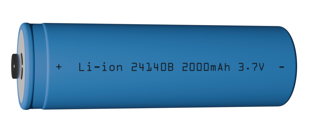
A Li-Ion cell#
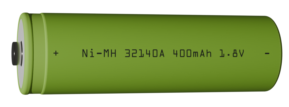
A Ni-MH cell#
During a competition run, teams will be required to complete a certain number of kits and/or modules as determined by the trial.
A kit is a grouping of four EV battery cells placed onto a tray.
A module is a unit of four EV battery shells arranged with a top and bottom shells and electrically connected with welds.
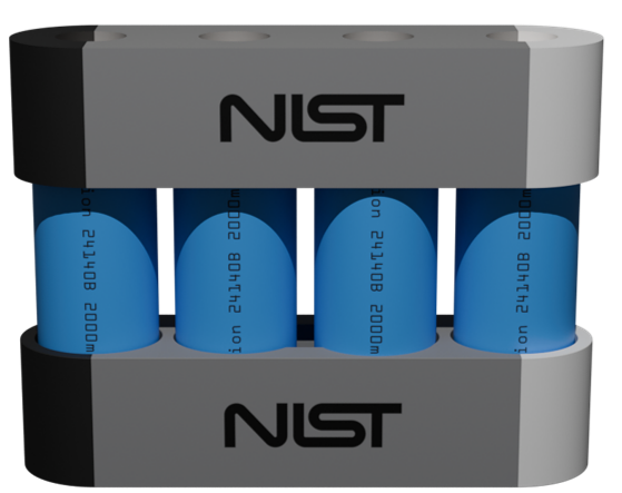
A fully constructed module#
The scenario is broken down into two main tasks:
Task 1: Inspection and Kit Building
Task 2: Module Construction
Task 1#
Task 1 involves inspecting the individual cells and arranging them onto a tray on one of the environments AGVs.
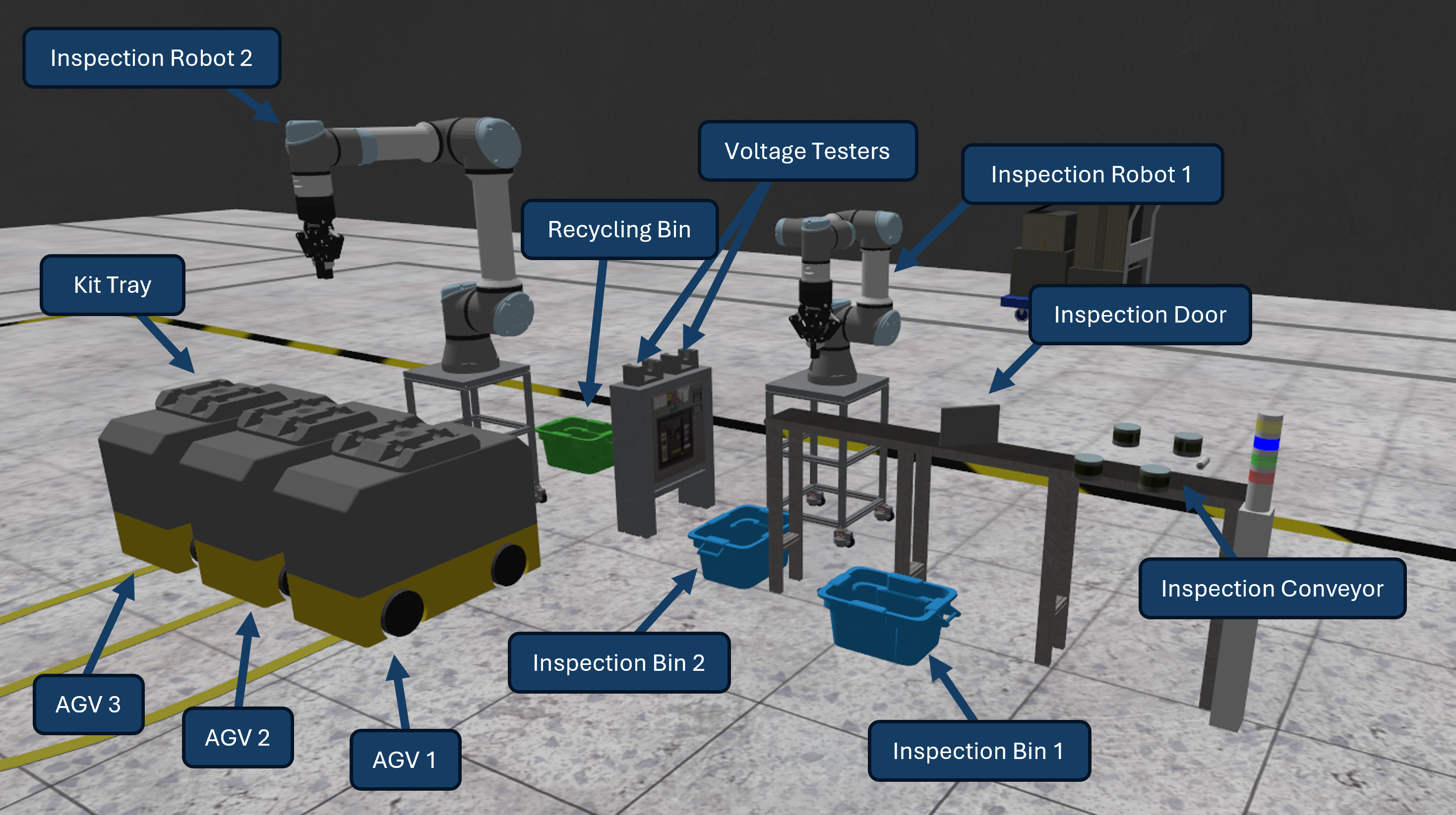
Task 1 annotated environment#
This task is broken into five steps:
Step 1a: Physical Inspection
Step 1b: Conveyor Pickup
Step 1c: Voltage Inspection
Step 1d: AGV Placement
Step 1e: Move AGV
Step 1a: Physical Inspection#
The conveyor speed and feed rate for the inspection conveyor are set by the team in their configuration file. After the competition is started, a service will become available to control the cell feed type for the inspection conveyor. Available types are in CellTypes.msg. Sending NONE will disable the cell feed.
For each cell, teams must use LIDAR point cloud data to reconstruct the cell geometry as it passes by on the conveyor to determine whether the cell is defective. A good cell should be completely cylindrical with smooth surfaces.
Defect Detection and Inspection Report Submission:
Teams should use LIDAR sensors to capture point cloud data and reconstruct a 3D model of each cell. Defective cells can exhibit one of three types of defects:
Dent: An area of the cell that is inset from the normal cylindrical surface. Dents are roughly spherical depressions in the cell body.
Scratch: An area of the cell that is inset from the normal surface. Scratches are long and narrow depressions that typically run along the length of the cell.
Bulge: An area of the cell that is offset outward from the normal cylindrical body. Bulges are roughly spherical protrusions extending beyond the expected cell surface.
Note
All defects will be at least 2mm removed from the normal cell surface at their furthest point, ensuring they are detectable using LIDAR point cloud analysis.
After the inspection is complete, an inspection report must be submitted by the team using the submit inspection report service. The inspection report contains:
passed: A boolean indicating whether the cell passed inspection (true for good cells, false for defective cells)
defects: An array of CellDefect messages, one for each detected defect
For each detected defect, teams must populate a CellDefect message with:
defect_type: The type of defect (DENT=1, BULGE=2, or SCRATCH=3)
theta: The azimuthal angle of the defect centroid around the cell circumference. Set to zero (0) when the defect is inline with the direction of the conveyor. Follow the right-hand rule where positive angles correspond to upward rotation in the z-direction.
z: The height of the defect centroid relative to the bottom of the cell (cell base). The radial component (r) is implied as the radius of the cell.
Note
Classifying defects is optional. Teams can simply report that a cell is defective without providing detailed defect information. However, correctly classifying defects provides bonus points (see Inspection Classification bonus in the scoring section).
If the cell passes inspection, the inspection door will open allowing the cell to proceed. If the cell fails inspection, it will drop into the bin next to the conveyor.
Inspecting a cell#
Warning
If a non-faulty cell drops into the bin, the team will incur a penalty
Step 1b: Conveyor Pickup#
After a non-faulty cell passes through the inspection door it must be picked up by inspection robot 1, a UR3e equipped with a robotiq 2f-85 gripper. The gripper is controlled using the gripper command action. After the cell is grasped it is placed into one of the two available voltage testers.
Picking a cell from the conveyor and placing into the voltage tester#
Warning
If the robot collides with any object in the environment other than a cell the team will incur a penalty.
Step 1c: Voltage Inspection#
Once a cell is placed in the voltage tester, the tester publishes a voltage reading to a topic.
Note
The testers publish with a small amount of noise so it is best to take readings over a short time period and average the results.
Step 1d: AGV Placement#
After voltage inspection, the cell should be picked by inspection robot 2 (a UR5e with robotiq 2f-85 gripper). If the cell voltage is outside the tolerance of \(\pm 0.2 V\) it must be placed into the recycling bin. If a cell voltage is within spec it should be placed onto a tray on one of the available AGVs.
Completed kits must meet a specified voltage tolerance based on the nominal cell voltages and tolerance values defined for each cell type:
Before moving the AGV, call the check kit quality service to ensure that the kit on the AGV tray is good.
Placing cells onto an AGV tray#
Note
Cells lock to the tray after they are placed and cannot be moved at the inspection station.
Warning
If two robots collide with each other the collision penalty is incurred twice.
Step 1e: Move AGV#
There are four possible stations for the AGVs (Inspection, Assembly, Shipping, Recycling)
To complete a kitting order the AGV with a completed tray must be moved to the shipping station. AGV motion is controlled through the move agv action. When the AGV arrives the submit kit service should be called, at this point the kit will be evaluated to ensure that all four cells are non-defective, within voltage spec, of the same cell type, and the total kit voltage is correct. If the kit is accepted the tray will be cleared and the AGV can be sent back to the inspection station. If the kit is not accepted the AGV must be sent to the recycling station. When the AGV is at the recycling station a service can be called to recycle the tray which clears the cells and allows the AGV to be used again.
To complete a module order the AGV should be moved the assembly station where task 2 can begin.
Moving AGV1 to the shipping station and submitting the kit#
Warning
If two AGVs collide with each other the team will incur a penalty.
Task 2#
Task 2 involves constructing a module from a completed kit.
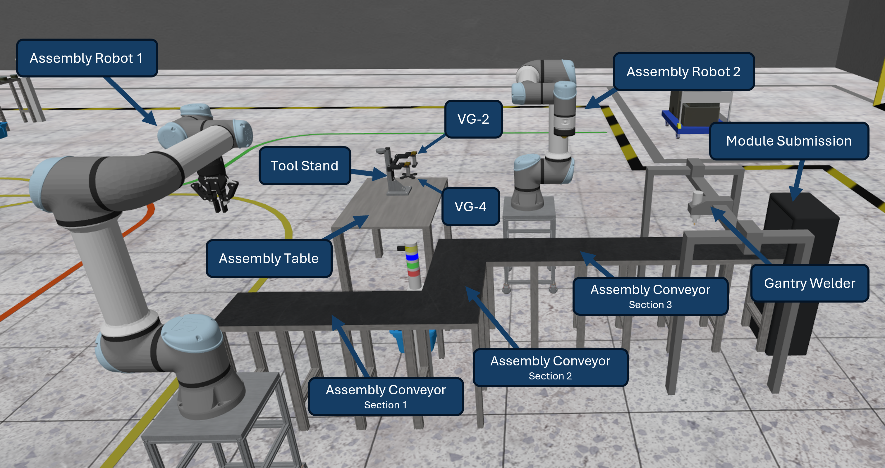
Task 2 annotated environment#
This task is broken into six steps:
Step 2a: Cell Installation
Step 2b: Tool Change
Step 2c: Top Shell Installation
Step 2d: Top Welds
Step 2e: Module Flip
Step 2f: Bottom Welds
Step 2a: Cell Installation#
When an AGV arrives at the assembly station, module construction can begin. The first step is to insert a new bottom shell into the environment using a service call. The shell will always spawn in the same place.
Cells should be picked using assembly robot 1 (a UR5e equipped with a robotiq 2f-85 gripper) and placed into each of the four slots in the bottom shell. The cells must be properly oriented. The central hole in the AGV tray can optionally be used to perform a re-grasp of the cell.
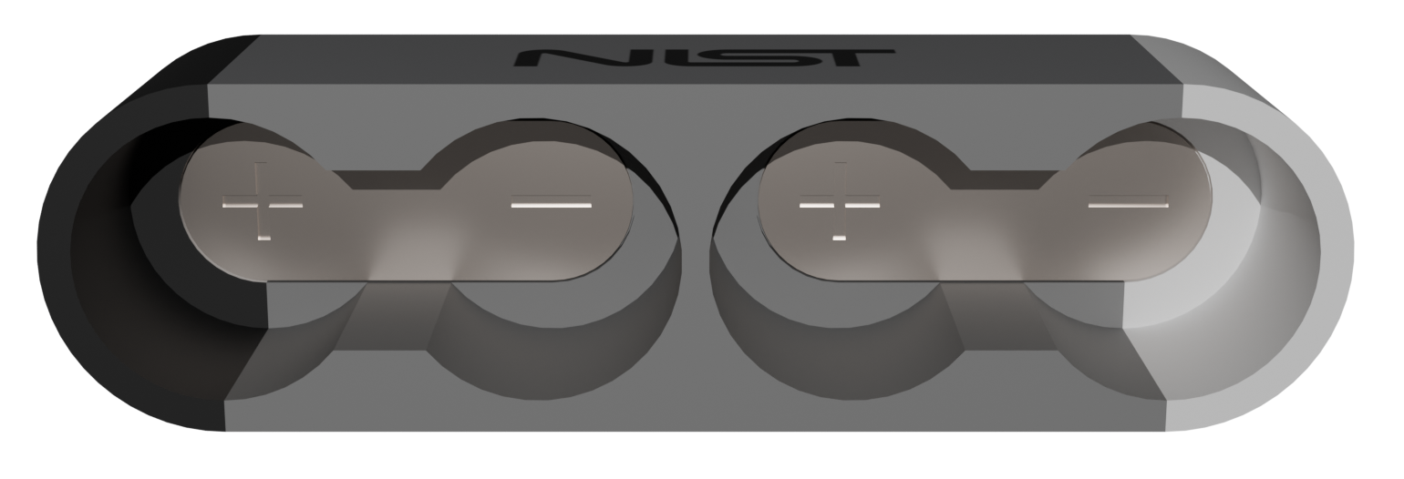
Shells are marked with + or - to indicate cell polarity direction#
Installing cells into bottom shell#
Note
The central hole in the AGV tray will automatically center the cell when the cell contacts the bottom of the hole to make alignment easier.
Note
Cells lock to bottom shell when placed.
Step 2b: Tool Change#
Assembly robot 2 is equipped with a coupler that allows it to utilize one of two vacuum gripper tools (VG2 or VG4). To change tools the coupler should be moved to the location of the desired tool and the attach tool service will lock the tool to the robot. For the next step assembly robot 2 must attach VG2 which is capable of picking up a top shell. The tool must then be maneuvered away from the tool stand without colliding.
Performing tool change operation#
Note
The arrows on the tool coupler and tool must be aligned in order to successfully pick up a tool.
Step 2c: Top Shell Installation#
Unlike the inspection conveyor which is constantly moving, the assembly conveyor is broken up into three sections that can be moved independently. Section 1 and 2 can be moved forward and section 3 can be moved forward and backwards. After all four cells are installed to the bottom shell the team should use the section 1 and section 2 conveyors to move the partially completed module until it reaches section 3.
The next step is to insert a new top shell into the environment using a service call. The shell will spawn at a random location and orientation on the assembly table. Teams must use sensor(s) to determine its location before picking. Assembly robot 2 must then pick up the top shell from the assembly table and place it onto the partial module.
Installing top shell onto partial module#
Note
Both suction cups must be in contact with the top shell in order to grasp it.
Note
The black and white bands on the top and bottom shell should be aligned.
Step 2d: Top Welds#
With the top shell in place, teams must perform four welds to electrically connect the cells. The module should be moved to underneath the gantry welder using the section 3 conveyor. The gantry welder is a 3-DOF gantry with a set of welder electrodes at the tool. These electrodes must be in contact with the weld plate embedded in the shell before a proper weld can be performed through a service call.
Performing top welding operations#
Step 2e: Module Flip#
After completing the top welds, the entire module must be flipped in order to provide access to perform the bottom welds. Assembly robot 2 must perform another tool change operation to return VG2 to the tool stand and pick up VG4.
The module should be moved back to assembly robot 2 using the section 3 conveyor and grasped from the side. It should then be flipped and returned to the conveyor belt.
Flipping module to access bottom connections#
Note
Two of the suction cups must be in contact with the top shell and the other two must be in contact with the bottom shell in order to grasp the module.
Warning
If the module or any components of the module drop on the floor or any other invalid surface the team will incur a penalty
Step 2f: Bottom Welds#
The final step involves performing welding operations on the bottom connections to complete the electrical circuit of the module. This completes the module construction process. The module can then be moved to the end of the conveyor to the submission area and the submit module service can be called.
Performing bottom welding operations#
Note
The module will be removed from the environment
Competition Flow#
The competition follows a structured workflow with distinct states and phases. The flowchart below illustrates the complete competition lifecycle from preparation to completion.
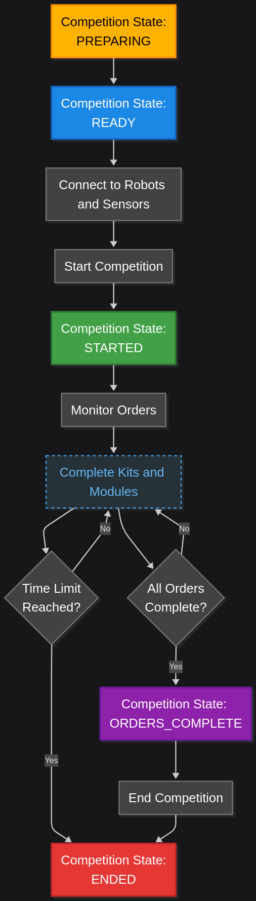
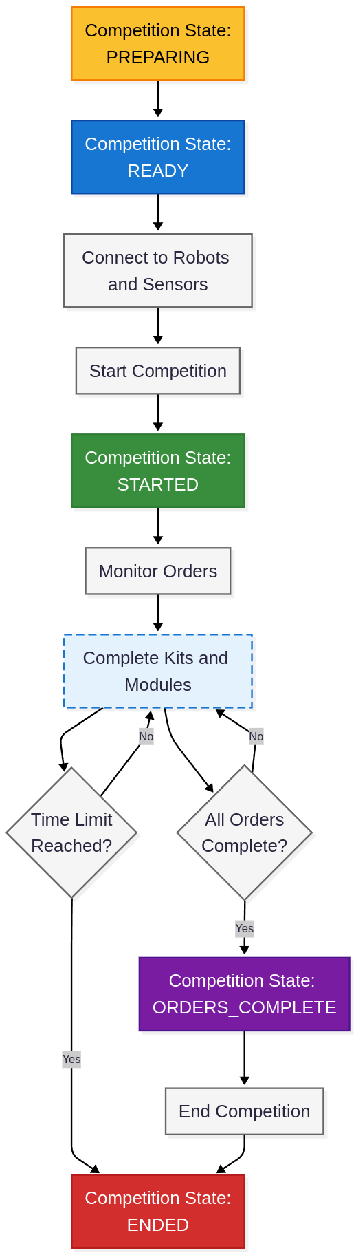
Competition States
The competition progresses through five distinct states:
PREPARING - Initial state where the simulation environment is being set up
READY - Environment is fully initialized and waiting for teams to connect
STARTED - Active competition phase where teams execute their solutions
ORDERS_COMPLETE - All required orders have been successfully completed
ENDED - Competition has concluded
Competition Flow
Setup Phase: Once the competition state reaches READY, teams must connect to all robots and sensors in the environment. This ensures proper communication channels are established before production begins.
Start Competition: Teams initiate the competition through a service call, transitioning the state to STARTED.
Production Phase: Teams monitor incoming orders and execute the complete production workflow:
Task 1: Inspect cells, build kits, and deliver to shipping or assembly stations
Task 2: Construct modules from completed kits (when applicable)
Competition End: The competition ends when the time limit is reached or when teams manually end it through a service call. When all orders are complete, the state changes to ORDERS_COMPLETE as a signal to teams that they have finished everything required.
Important
The competition state will not change to ORDERS_COMPLETE if there is still a high priority order to be announced.