Abstract class Grating
The abstract class Grating is used by RCW_Model and RCW_BRDF_Model to describe a periodic grating. There are several instantiable models currently available that inherit Grating:
- Generic_Grating: A grating described by a grating description file. This description is the most general and can describe nearly any grating.
- Sinusoidal_Relief_Grating: A grating having a sinusoidal relief profile.
- Triangular_Grating: A grating having a triangular profile.
- Corner_Rounded_Grating: A trapezoidal grating with rounded corners.
- Single_Line_Grating: A trapezoidal grating.
- Sinusoidal_Volume_Grating: A volume grating with a sinusoidal variation in the dielectric function.
- Dielectric_Stack_Grating: A trivial grating consisting of a stack of films, possibly anisotropic and/or magnetic.
- Overlaid_Grating: Two gratings, one on top of the other.
Grating provides RCW_Model with the number of layers in a grating, the thickness of each layer, the materials above and below the grating, and the the Fourier expansion coefficients for the dielectric function in each layer.
Instantiable Models and Their Parameters:
| Parameter | Data Type | Description | Default |
|---|---|---|---|
|
Generic_Grating: A grating described by a grating definition file. The format of this file is described below. The fiducial (where x=0) is defined by the coordinates used in the definition. |
|||
| period | double | The period of the grating [µm]. This parameter is overridden by a period specified in the file. (Inherited from Grating.) |
1 |
| medium_i | dielectric_function | The
optical constants of the incident medium, expressed as
a complex number (n,k) or, optionally, as a function of
wavelength. The material must be non-absorbing
(k=0). (Inherited from Grating.) |
(1,0) |
| medium_t | dielectric_function | The
optical constants of the transmitting medium (usually
the substrate), expressed as a complex number (n,k) or,
optionally, as a function of wavelength. (Inherited from Grating.) |
(4.05,0.05) |
| filename | string | The name
of the file containing the grating description. The
format of the file is described below. |
no default |
| pstring | string | A string containing a comma-delimited list of the parameter values enclosed in
parentheses. See below. |
no default |
| nlayers | int | The approximate number of levels to be used in the staircase approximation.
This value may differ from the actual value due to round-off error or other considerations.
See below. |
20 |
|
Sinusoidal_Relief_Grating:
A grating consisting of a film having a sinusoidal relief profile. The fiducial (where x=0) is defined by the location of the highest point of the sinusoid. 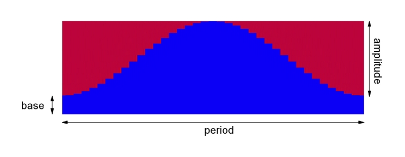
|
|||
| period | double | The
period of the grating [µm]. (Inherited from Grating.) |
1 |
| medium_i | dielectric_function | The
optical constants of the incident medium, expressed as
a complex number (n,k) or, optionally, as a function of
wavelength. The material must be non-absorbing
(k=0). (Inherited from Grating.) |
(1,0) |
| medium_t | dielectric_function | The
optical constants of the transmitting medium (usually
the substrate), expressed as a complex number (n,k) or,
optionally, as a function of wavelength. (Inherited from Grating.) |
(4.05,0.05) |
| amplitude | double | The amplitude of the sinusoid, measured from peak to valley [µm]. | 0.4 |
| base | double | The thickness of extra material beneath the sinusoid [µm]. | 0 |
| option | int | This parameter defines whether the steps are evenly spaced horizontally (option=0 or vertically (option=1). | 0 |
| nlevels | int | The number of levels in the grating for the staircase approximation. | 20 |
| material | dielectric_function | The optical constants of the grating material, expressed as a complex number (n,k) or, optionally, as a function of wavelength. | (4.05,0.05) |
|
Triangular_Grating:
A grating having a triangular profile The fiducial (where x=0) is defined as the midpoint of the base of the triangle. 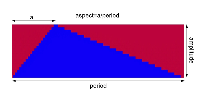
|
|||
| period | double | The
period of the grating [µm]. (Inherited from Grating.) |
1 |
| medium_i | dielectric_function | The
optical constants of the incident medium, expressed as
a complex number (n,k) or, optionally, as a function of
wavelength. The material must be non-absorbing
(k=0). Inherited from Grating. |
(1,0) |
| medium_t | dielectric_function | The
optical constants of the transmitting medium (usually
the substrate), expressed as a complex number (n,k) or,
optionally, as a function of wavelength. Inherited from Grating. |
(4.05,0.05) |
| material | dielectric_function | The optical constants of the grating material, expressed as a complex number (n,k) or, optionally, as a function of wavelength. | (4.05,0.05) |
| amplitude | double | The
peak-to-valley amplitude of the
grating. |
0.4 |
| aspect | double | The aspect ratio of the triangle. For aspect=0.5, the grating is symmetric. | 0.5 |
| nlevels | int | The number of levels in the grating for the staircase approximation. | 20 |
|
Corner_Rounded_Grating:
A trapezoidal grating with rounded
corners. The fiducial (where x=0) is defined as the middle of the line. 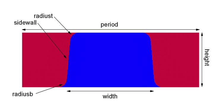
|
|||
| period | double | The
period of the grating [µm]. (Inherited from Grating.) |
1 |
| medium_i | dielectric_function | The
optical constants of the incident medium, expressed as
a complex number (n,k) or, optionally, as a function of
wavelength. The material must be non-absorbing
(k=0). (Inherited from Grating.) |
(1,0) |
| medium_t | dielectric_function | The
optical constants of the transmitting medium (usually
the substrate), expressed as a complex number (n,k) or,
optionally, as a function of wavelength. (Inherited from Grating.) |
(4.05,0.05) |
| material | dielectric_function | The optical constants of the grating material, expressed as a complex number (n,k) or, optionally, as a function of wavelength. | (4.05,0.05) |
| height | double | The
height of the line in the grating
[µm]. |
0.1 |
| width | double | The base width of the trapezoid, before rounding the corners [µm]. | 0.1 |
| sidewall | double | The sidewall angle of the trapezoid, before corner rounding [degrees]. | 88 |
| radiust | double | The radius of curvature of the top corners of the trapezoid [µm]. | 0.01 |
| radiusb | double | The radius of curvature of the bottom corners of the trapezoid [µm]. | 0.001 |
| nlevels | int | The number of levels in the grating for the staircase approximation. | 10 |
|
Single_Line_Grating:
A trapezoidal grating. The fiducial (where x=0) is defined as the middle of the top of the line. 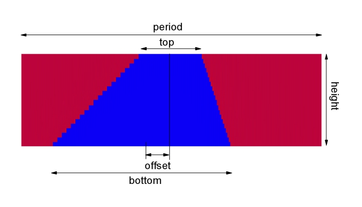
|
|||
| period | double | The
period of the grating [µm]. (Inherited from Grating.) |
1 |
| medium_i | dielectric_function | The
optical constants of the incident medium, expressed as
a complex number (n,k) or, optionally, as a function of
wavelength. The material must be non-absorbing
(k=0). (Inherited from Grating.) |
(1,0) |
| medium_t | dielectric_function | The
optical constants of the transmitting medium (usually
the substrate), expressed as a complex number (n,k) or,
optionally, as a function of wavelength. (Inherited from Grating.) |
(4.05,0.05) |
| material | dielectric_function | The optical constants of the grating material, expressed as a complex number (n,k) or, optionally, as a function of wavelength. | (4.05,0.05) |
| space | dielectric_function | The optical constants of the material between the trapezoid, expressed as a complex number (n,k) or, optionally, as a function of wavelength. | (1,0) |
| height | double | The
height of the line in the grating
[µm]. |
0.2 |
| bottomwidth | double | The base width of the trapezoid [µm]. | 0.2 |
| topwidth | double | The top width of the trapezoid [µm]. | 0.2 |
| offset | double | The offset of the top of the trapezoid compared to the bottom [µm]. | 0 |
| nlevels | int | The number of levels in the grating for the staircase approximation. | 10 |
|
Sinusoidal_Volume_Grating:
A volume grating consisting of a film, whose dielectric function varies sinusoidal along the grating direction. The fiducial (where x=0) is defined as the location of the maximum index at the top of the grating. 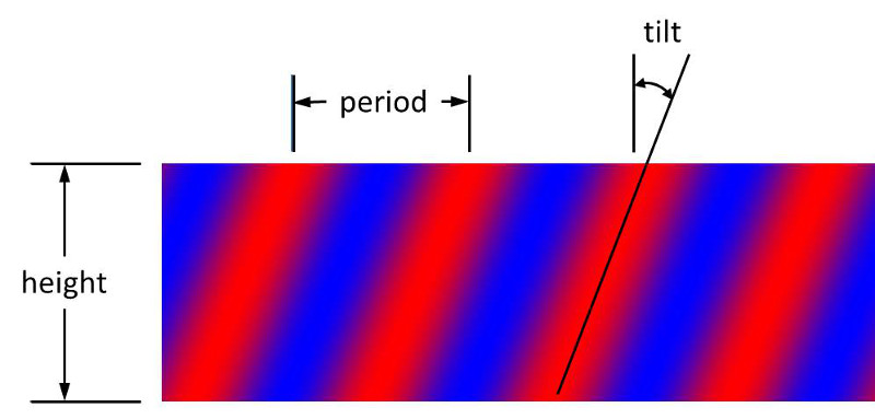
|
|||
| period | double | The
period of the grating [µm]. (Inherited from Grating.) |
1 |
| medium_i | dielectric_function | The
optical constants of the incident medium, expressed as
a complex number (n,k) or, optionally, as a function of
wavelength. The material must be non-absorbing
(k=0). (Inherited from Grating.) |
(1,0) |
| medium_t | dielectric_function | The
optical constants of the transmitting medium (usually
the substrate), expressed as a complex number (n,k) or,
optionally, as a function of wavelength. (Inherited from Grating.) |
(4.05,0.05) |
| minimum | dielectric_function | The optical constants of the grating material associated with the troughs in the dielectric function, expressed as a complex number (n,k) or, optionally, as a function of wavelength. | (1.50,0) |
| maximum | dielectric_function | The optical constants of the grating material associated with the peaks in the dielectric function, expressed as a complex number (n,k) or, optionally, as a function of wavelength. | (1.52,0) |
| thick | double | The thickness of the
volume grating.
[µm]. |
0.1 |
| tilt | double | The tilt angle of the volume grating [degrees]. When the value of tilt is 0, the dielectric function varies only in the grating direction. When it is non-zero, the dielectric function also varies with vertical position in the grating. | 0 |
| nlevels | int | The number of levels the grating is divided into for the staircase approximation. | 1 |
Dielectric_Stack_Grating:
A grating consisting only of a stack of films. The films can be diagonally anisotropic and/or magnetic.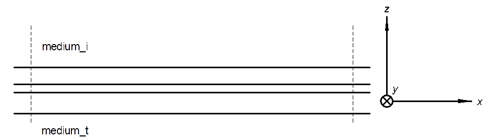
|
|||
| period | double | The
period of the grating [µm]. (Inherited from Grating.) |
1 |
| medium_i | dielectric_function | The
optical constants of the incident medium, expressed as
a complex number (n,k) or, optionally, as a function of
wavelength. The material must be non-absorbing
(k=0). (Inherited from Grating.) |
(1,0) |
| medium_t | dielectric_function | The
optical constants of the transmitting medium (usually
the substrate), expressed as a complex number (n,k) or,
optionally, as a function of wavelength. (Inherited from Grating.) |
(4.05,0.05) |
| stackepsx | StackModel_Ptr | The description of any film stacks on the substrate. This particular stack corresponds to the dielectric function in the x direction (the grating direction). | No_StackModel |
| stackepsy | StackModel_Ptr | The description of any film stacks on the substrate. This particular stack corresponds to the dielectric function in the y direction (the grating direction). If this parameter is set, it must have the same number of layers and the same layer thicknesses as stackepsx and stackepsz must be set, too. If this parameter is not set (No_StackModel), then the materials are taken to be isotropic and the dielectric functions taken from stackepsx. | No_StackModel |
| stackepsz | StackModel_Ptr | The description of any film stacks on the substrate. This particular stack corresponds to the dielectric function in the z direction (the grating direction). If this parameter is set, it must have the same number of layers and the same layer thicknesses as stackepsx and stackepsy must be set, too. If this parameter is not set (No_StackModel), then the materials are taken to be isotropic and the dielectric functions taken from stackepsx. | No_StackModel |
| stackmux | StackModel_Ptr | The description of any film stacks on the substrate. This particular stack corresponds to the magnetic function in the x direction (the grating direction). If this parameter is set, it must have the same number of layers and the same layer thicknesses as stackepsx. If this parameter is not set (No_StackModel), any layers are taken to be nonmagnetic. | No_StackModel |
| stackmuy | StackModel_Ptr | The description of any film stacks on the substrate. This particular stack corresponds to the magnetic function in the y direction (the grating direction). If this parameter is set, it must have the same number of layers and the same layer thicknesses as stackepsx, and stackmuz must be set, too. If this parameter is not set (No_StackModel), any layers are taken to be isotropic. | No_StackModel |
| stackmuz | StackModel_Ptr | The description of any film stacks on the substrate. This particular stack corresponds to the magnetic function in the z direction (the grating direction). If this parameter is set, it must have the same number of layers and the same layer thicknesses as stackepsx, and stackmuy must be set, too. If this parameter is not set (No_StackModel), any layers are taken to be isotropic. | No_StackModel |
|
Overlaid_Grating:
One grating on top of another. Two gratings with identical periods are specified, one designating the structure on top and the other designating the structure
underneath it. A separation distance between the two and an overlay distance is specified. The fiducial (where x=0) of the grating is defined by that of the lower grating. 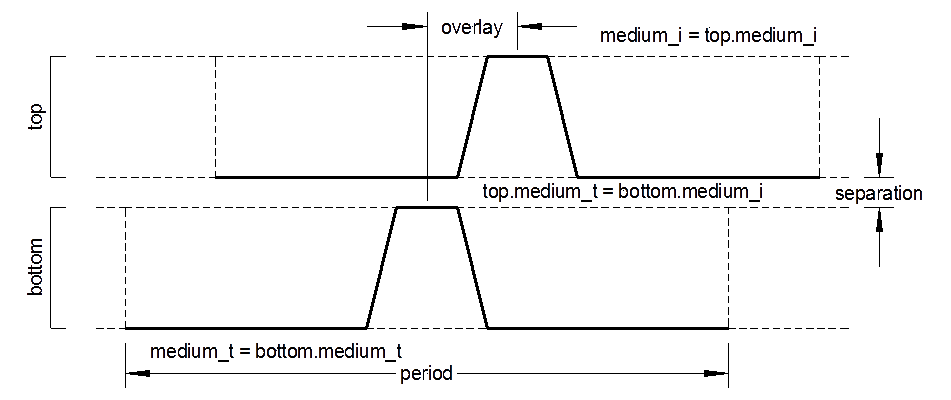
|
|||
| period | double | The period of the grating [µm]. (Inherited from Grating.) |
1 |
| medium_i | dielectric_function | The
optical constants of the incident medium, expressed as
a complex number (n,k) or, optionally, as a function of
wavelength. The material must be non-absorbing
(k=0). (Inherited from Grating.) |
(1,0) |
| medium_t | dielectric_function | The
optical constants of the transmitting medium (usually
the substrate), expressed as a complex number (n,k) or,
optionally, as a function of wavelength. (Inherited from Grating.) |
(4.05,0.05) |
| top | Grating_Ptr | The grating on the top. This grating's period must match the period of the Overlaid_Grating. The incident medium must match medium_i. | Single_Line_Grating |
| bottom | Grating_Ptr | The grating on the bottom. This grating's period must match the period of the Overlaid_Grating. This grating's medium_i must match the above grating's medium_t. This grating's medium_t must match the medium_t of the Overlaid_Grating. | Single_Line_Grating |
| overlay | double | The lateral shift of the top grating relative to the bottom grating [µm]. This shift is with respect to the fiducial for each grating, which may differ from one grating type to another. | 0 |
| separation | double | The vertical separation distance between the two gratings [µm]. This material is that of the bottom grating's medium_i, which must match the top grating's medium_t. | 0 |
See also:
SCATMECH Home, RCW_Model, RCW_BRDF_Model
Include file:
#include "grating.h"
Source code:
grating.cpp
Definition of public and protected elements
class Grating : public Model {
    public:
        virtual COMPLEX fourier(int order,int level,int recip=0) = 0;
        virtual int get_levels()=0;
        virtual double get_thickness(int level) = 0;

        void set_lambda(double _lambda);
        double get_lambda();

    protected:
        COMPLEX epsilon(const dielectric_function& e);
        double lambda;
};
virtual COMPLEX fourier(int order,int level,int recip=0) = 0
This virtual function must be defined for every model inheriting Grating and returns the fourier coefficient of either the dielectric function (for recip=0) or the inverse of the dielectric function (for recip=1) for order order and level level. Level 0 is the level closest to the incident light.
virtual int get_levels()=0
This virtual funciton must be defined for every model inheriting Grating and returns the number of layers in the grating.
virtual double get_thickness(int level) = 0
This virtual funciton must be defined for every model inheriting Grating and returns the thickness of level level, which must be non-negative.
void set_lambda(double _lambda)
double get_lambda()
double lambda
The wavelength of the light and functions to set and get it. It is necessary to set this parameter so that the optical properties of the different materials can be set to that for the correct wavelength.
COMPLEX epsilon(const dielectric_function& e)
Function that returns the dielectric function of the material e evaluated at lambda.
File format for Generic_Grating
This section describes the file format required by Generic_Grating. The file is a text file. We will illustrate the format of the file using an example grating structure, shown below. The example structure is symmetric, so some dimensions are not shown. Dimensions are generic and parameters can be passed to the model at a later time using the pstring parameter. The example structure consists of a semiconductor line above a thin film, surrounded by an isolation material.
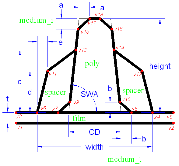
It is helpful, when writing a grating description, to make a diagram, such as that shown above, label all the parameters that could be free parameters (as done in blue, sans-serif type in the figure), label all regions with their materials (as done in green, roman type in the figure), and label all vertices (as done in red, slanted sans-serif type in the figure). Each of these items should be given unique names. All boundaries between materials must be straight line segments, so if any of the boundaries are curved, they will need to be broken up into segments. The material above the grating should be labeled medium_i, and the material below the grating should be labeled medium_t.
There are five blocks (one is optional) of data in the file, and each begins with the name of the block and ends with the word END. In the following, the five blocks are described. In the text file, these blocks of data are listed consecutively and in order. Comments can be located anywhere in the file, are delimited by a semicolon (;), and run to the end of the line.
PARAMETERS block:
The first block of data contains a list of the parameters for the structure. The number of parameters determines the number of values that must be passed to the parameter pstring at run time. The order of the parameters given in pstring must be the same as that listed in the PARAMETERS block. For the example structure above, we would use,
	      PARAMETERS
	      height     ; The height of the structure
	      CD         ; The critical dimension
	      a          ; Corner rounding at the top of the line
	      b          ; Corner rounding at the bottom of the line
	      c          ; The height of the isolation material
	      width      ; The total width of the structure
	      d          ; Height of kink in isolation material
	      e          ; Horizontal offset of kink in isolation material
	      t          ; The thickness of the oxide
	      SWA        ; The sidewall angle (degrees)
	      n1         ; The refractive index of the isolation material
	      END
which specifies that the model requires 11 parameters. Notice that one parameter, n1 is not shown in the figure, and corresponds to the index of refraction of the isolation material. If pstring is given the value
"(0.2,0.1,0.01,0.01,0.15,0.3,0.1,0.02,0.02,85,1.8)"then height will be given the value 0.2, CD will be given the value 0.1, etc. Also notice that the file can have any number of optional comments, which begin with semicolons and extend to the end of a line.
WORKING block:
The WORKING block is an optional block of instructions that is used to define temporary variables and calculate intermediate values used in subsequent calculations. The block contains pairs of strings: the first in each pair represents an indentifier for a variable, while the second contains an arithmetic expression for that value. The arithmetic expression can use any of the parameters previously defined in the WORKING block, parameters defined in the PARAMETERS block, plus the additional parameters period or lambda. For our example, we use
	      WORKING
	      tanSWA   tand(SWA)
	      cotSWA   if(tanSWA,1/tanSWA,0)   ; The cotangent of the angle
	      x1      -period/2
	      x2      period/2
	      x3      x1
	      x4      width/2
	      x5      x2
	      x6      -x4
	      x7      -CD/2-b
	      x8      -x7
	      x9      -CD/2+b*cotSWA
	      x10     -x9
	      x11     x6+e
	      x12     -x11
	      x13     -CD/2+c*cotSWA
	      x14     -x13
	      x15     -CD/2+(height-a)*cotSWA
	      x16     -x15
	      x17     -CD/2+height*cotSWA+a
	      x18     -x17
	      y1      -t
	      y2      -t
	      y3      0
	      y4      0
	      y5      0
	      y6      0
	      y7      0
	      y8      0
	      y9      b
	      y10     b
	      y11     d
	      y12     d
	      y13     c
	      y14     c
	      y15     height-a
	      y16     y15
	      y17     height
	      y18     height
	      END
The expressions should not contain spaces, unless they are surrounded by parentheses. Notice that the expressions can be quite complicated, too. Many common functions and operations are available. For trigonometric functions, there are additional functions ending with the letter d, which take arguments or return results in degrees rather than radians.
A useful function that is available is the table expression: @file(x,icol). This function evaluates a table of values in the file file, at x using column icol. For example, if glass is a file containing the optical properties for glass, @glass(lambda,2) will return the index of refraction evaluated at the wavelength.
MATERIALS block:
The second block of data contains a list of materials used in the structure. For isotropic materials, each material is specified by a pair of strings. The first string is a name, which will be used later to refer to that material. The second string will be a value sent to dielectric_function, which can be a complex number or a filename, and specifies the index of refraction of the material. The complex number may be specified as an expression using the parameters above, plus the additional parameters period or lambda. Two materials are predefined: medium_i and medium_t, which correspond to the materials above and below the grating, respectively. For the example given above, we might use
	      MATERIALS
	      poly   polysilicon
	      spacer (n1,0)
	      film   oxide
	      END
The first (poly) will obtain the complex index from a file named polysilicon. The second (spacer) will be non-absorbing, with an index given by the parameter n1. Finally, the third (film) will obtain the complex index from a file named oxide.
Notice that the expressions for the complex index of refraction can be quite complicated. This allows the user to specify a functional form for a material. For example, process variations can be specified with a parameter x:
	      MATERIALS
	    material   (@MaterialA(lambda,2)*x+@MaterialB(lambda,2)*(1-x),
                        @MaterialA(lambda,3)*x+@MaterialB(lambda,3)*(1-x))
	      END
Here, MaterialA and MaterialB are two files containing the optical properties of two materials, and the parameter x specifies the extent the actual material behaves like one or the other.
Materials can be defined to be anisotropic, magnetic, or anisotropic and magnetic using the keywords ANISO, MAGNETIC, and ANISOMAGNETIC, respectively:
	       MATERIALS
	       ANISO materialA indexx indexy indexz
	       MAGNETIC materialB sqrteps sqrtmu
	       ANISOMAGNETIC materialC sqrtepsx sqrtepsy sqrtepsz sqrtmux sqrtmuy sqrtmuz
	       END
In the above example for ANISO, materialA is the name of the material, and indexx, indexy, and indexz are the indices of refraction in the x, y, and z directions, respectively.
In the above example for MAGNETIC, materialB is the name of the material, sqrteps is the square root of the dielectric function, and sqrtmu is the square root of the magnetic function.
In the above example for ANISOMAGNETIC, materialC is the name of the material, sqrtepsx, sqrtepsy, and sqrtepsz are the square roots of the dielectric function in the x, y, and z directions, respectively, and sqrtmux, sqrtmuy, and sqrtmuz are the square roots of the magnetic function in the x, y, and z directions, respectively.
VERTICES block:
The third block contains a list of all of the vertices, giving each one a name and an (x,y) coordinate. The name is given first, followed by the (x,y) coordinate as a pair of expressions, separated by a comma and surrounded by parentheses. The expressions can use any of the parameters defined above, plus the additional parameters period or lambda. For our example, we use
	      VERTICES
	      v1 (x1,y1)
	      v2 (x2,y2)
	      v3 (x3,y3)
	      v4 (x4,y4)
	      v5 (x5,y5)
	      v6 (x6,y6)
	      v7 (x7,y7)
	      v8 (x8,y8)
	      v9 (x9,y9)
	      v10 (x10,y10)
	      v11 (x11,y11)
	      v12 (x12,y12)
	      v13 (x13,y13)
	      v14 (x14,y14)
	      v15 (x15,y15)
	      v16 (x16,y16)
	      v17 (x17,y17)
	      v18 (x18,y18)
	      END
BOUNDARIES block:
The final section specifies all of the line segments dividing regions of materials. Each line segment is specified by two vertices (defined in the VERTICES section above) and two materials (defined in the MATERIALS section above). The materials are defined in order from the left material to the right material as one travels from the first vertex to the second. The period and height of the structure is defined by the minimum and maximum coordinates of all of the boundaries. That is, the actual period overrides the parameter period. For our example, we would use
	      BOUNDARIES
	      v1   v2   film      medium_t
	      v3   v6   medium_i  film
	      v6   v7   spacer    film
	      v7   v8   poly      film
	      v8   v4   spacer    film
	      v4   v5   medium_i  film
	      v6   v11  medium_i  spacer
	      v11  v13  medium_i  spacer
	      v7   v9   spacer    poly
	      v9   v13  spacer    poly
	      v13  v15  medium_i  poly
	      v15  v17  medium_i  poly
	      v17  v18  medium_i  poly
	      v18  v16  medium_i  poly
	      v16  v14  medium_i  poly
	      v14  v12  medium_i  spacer
	      v12  v4   medium_i  spacer
	      v14  v10  spacer    poly
	      v10  v8   spacer    poly
	      END
Notes:
The thickness of the layers is determined by ordering all of the vertical coordinates specified to ensure that these distances are accurate and not discretized by the number of layers. The number of layers given in any sub-layer is determined by the largest horizontal distance traversed by a diagonal in that sub-layer (ignoring boundaries between identical materials).
It is up to the user to ensure that the line segments are consistent with one other. If the program finds a problem with the segment definitions, it will throw a SCATMECH_exception.
While the variable period will be assigned the value given by the parameter by the same name, the actual period of the grating will be defined by the extent of the grating defined in the BOUNDARIES section.
The vertical coordinates may be referenced to any level, and one may choose whichever level is convenient to call zero. However, RCW_Model will always reference fields to the top of the grating, no matter what the vertical coordinate was in the file.
For More Information
SCATMECH Technical Information and Questions
Sensor Science Division Home Page
Sensor Science Division Inquiries
Website Comments
Current SCATMECH version: 7.22 (April 2021)