Abstract class CrossGrating
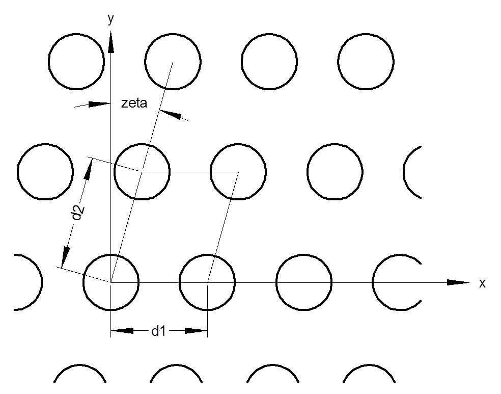
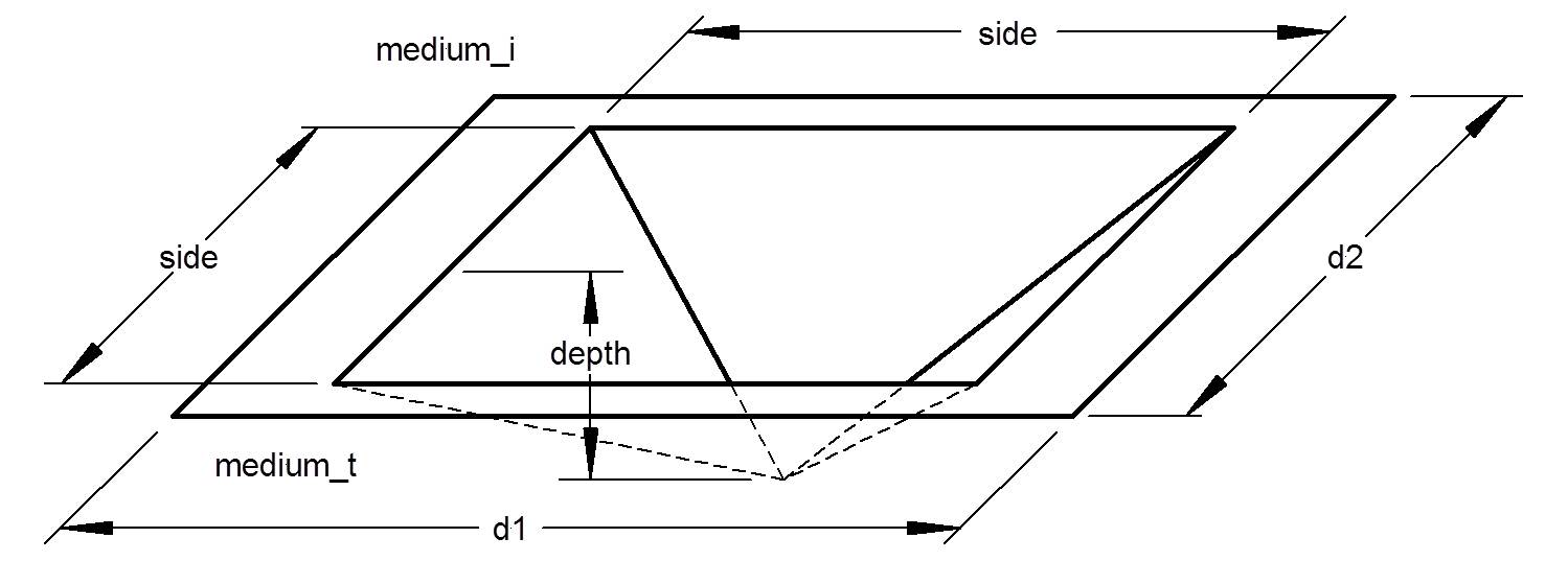
The abstract class CrossGrating is used by CrossRCW_Model to describe a two-dimensionally periodic grating. A crossed grating is a grating with periodicity along two directions. The diagram below shows a simple two-dimensionally periodic structure (crossed grating), with the grating constants, d1 and d2. The grating directions make an angle zeta from perpendicular.
There are several instantiable models currently available that inherit CrossGrating:
- OneD_CrossGrating: A cross grating defined by a one dimensional grating, using Grating.
- Overlaid_CrossGrating: A cross grating created by overlaying two other cross gratings.
- Overlaid_1D_CrossGrating: A cross grating created by overlaying two 1D gratings at a given angle.
- Null_CrossGrating: A trivial grating consisting of no features.
A number of CrossGratings inherit the properties of Gridded_CrossGrating, an abstract class that handles the Fourier factorization of the grating structure on a grid:
- Generic_CrossGrating: A crossed grating described by a grating description file. This description is the most general and can describe a wide variety of crossed gratinged with sharp material boundaries.
- Cylinder_CrossGrating: A cross grating described by an array of vertical cylinders.
- Rectangular_CrossGrating: A binary grating consisting of rectangles or parallelograms.
- Sphere_CrossGrating: A cross grating described by an array of spheres embeded in a medium.
- Pyramidal_Pit_CrossGrating: A cross grating described by an array of tetrahedral pits.
The CrossGratings that inherit Gridded_CrossGrating discretize the dielectric function on a uniform grid. These gratings are therefore approximations of the desired grating, and the results of CrossRCW_Model may not be continuous in the grating parameters.
Instantiable Models and Their Parameters:
| Parameter | Data Type | Description | Default |
|---|---|---|---|
OneD_CrossGrating:
A cross grating defined by a one dimensional grating, using Grating. The grating is aligned so that its grating vector is along the x direction
(see diagram above). The grating can be anisotropic, but not magnetic. 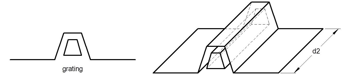 |
|||
| medium_i | dielectric_function | The
optical constants of the incident medium, expressed as
a complex number (n,k) or, optionally, as a function of
wavelength. The material must be non-absorbing
(k=0). (Inherited from CrossGrating.) This parameter must match grating.medium_i. | 1 |
| medium_t | dielectric_function | The
optical constants of the transmitted medium, expressed as
a complex number (n,k) or, optionally, as a function of
wavelength. (Inherited from CrossGrating.) This parameter must match grating.medium_t. | (4.05,0.05) |
| grating | Grating_Ptr | The one-dimensionally periodic grating. This grating can be anisotropic but not magnetic. | Single_Line_Grating |
| d2 | double | The lattice constant in the second direction [µm]. This parameter should have no effect, but a value is needed if this grating were overlaid with another cross grating using Overlaid_CrossGrating. The lattice constant in the first direction is obtained from the period of the grating (d1 = grating.period/cos(zeta)). | 0.5 |
| zeta | double | The off-perpendicular angle of the unit cell [deg]. The angle zeta is zero for a rectangular unit cell. This parameter should have no effect, other than to rotate the grating, but a value is needed if this grating were overlaid with another cross grating using Overlaid_CrossGrating. | 0 |
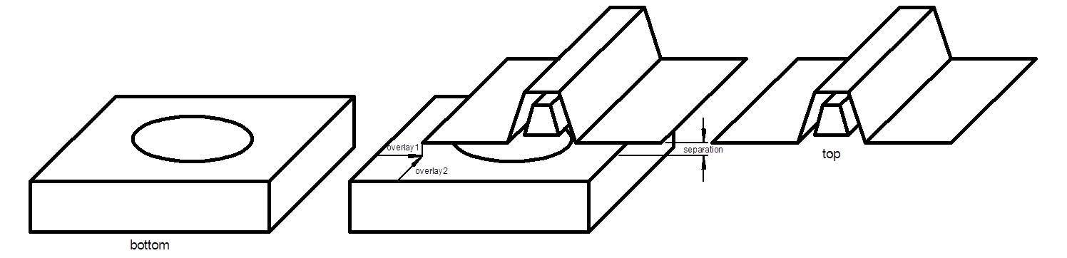
Overlaid_CrossGrating:
A grating created by overlaying two other crossed gratings. The two gratings must have identically shaped and
sized unit cells. Also, the medium_i of the bottom grating must match the medium_t of the top grating.
 |
|||
| medium_i | dielectric_function | The
optical constants of the incident medium, expressed as
a complex number (n,k) or, optionally, as a function of
wavelength. The material must be non-absorbing
(k=0). (Inherited from CrossGrating.) This parameter must match top.medium_i. | 1 |
| medium_t | dielectric_function | The
optical constants of the transmitted medium, expressed as
a complex number (n,k) or, optionally, as a function of
wavelength. (Inherited from CrossGrating.) This parameter must match bottom.medium_t. | (4.05,0.05) |
| top | CrossGrating_Ptr | The top grating (the one farther from the substrate). The parameter top.medium_i must match medium_i, and the parameter top.medium_t must match bottom.medium_i. The lattice parameters (d1, d2, and zeta must match those of bottom. |
OneD_CrossGrating |
| bottom | CrossGrating_Ptr | The bottom grating (the one closer to the substrate). The parameter bottom.medium_i must match top.medium_t, and the parameter bottom.medium_t must match medium_t. The lattice parameters (d1, d2, and zeta must match those of top. |
OneD_CrossGrating |
| overlay1 | double | The component of the overlay vector along the 1st coordinate [µm] | 0 |
| overlay2 | double | The component of the overlay vector along the 2nd coordinate [µm] | 0 |
| separation | double | The vertical separation between the bottom and top gratings [µm]. This separation is filled with bottom.medium_i, which must match top.medium_t. | 0 |
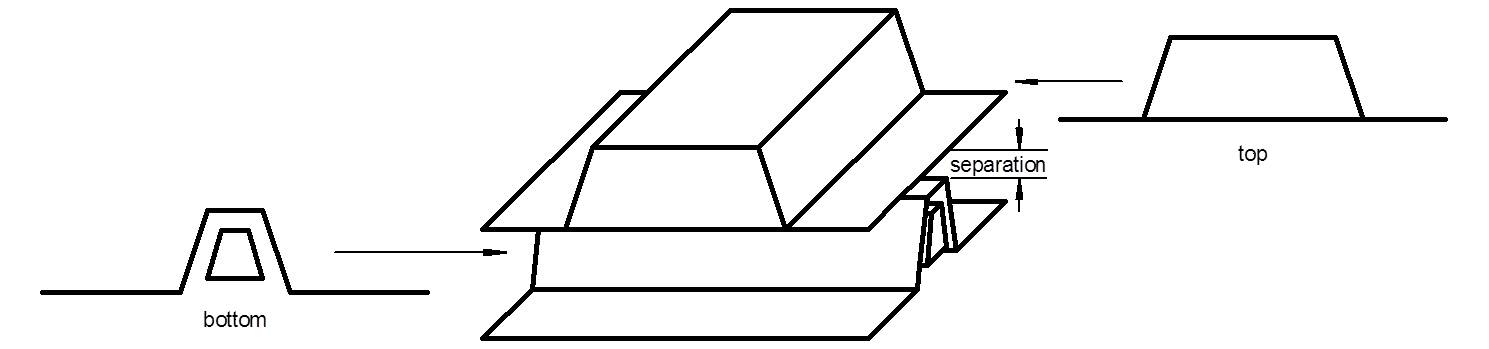
Overlaid_1D_CrossGrating:
A grating created by overlaying two one dimensional ratings at a given angle.
The medium_i of the bottom grating must match the medium_t of the top grating. The combined lattice parameters are d1=top.period/sin(angle),
d2=bottom.period/sin(angle), and zeta = 90-angle.
 |
|||
| medium_i | dielectric_function | The
optical constants of the incident medium, expressed as
a complex number (n,k) or, optionally, as a function of
wavelength. The material must be non-absorbing
(k=0). (Inherited from CrossGrating.) This must match top.medium_i. | 1 |
| medium_t | dielectric_function | The
optical constants of the transmitted medium, expressed as
a complex number (n,k) or, optionally, as a function of
wavelength. (Inherited from CrossGrating.) This must match bottom.medium_t. | (4.05,0.05) |
| top | Grating_Ptr | The top grating (the one farther from the substrate). The grating direction of this grating is aligned along the
second direction. The period is used to define the period along the second direction of the 2D grating.
The parameter top.medium_i must match medium_i, and the parameter top.medium_t must match bottom.medium_i. |
Single_Line_Grating |
| bottom | Grating_Ptr | The top grating (the one closer to the substrate). The grating direction of this grating is aligned along the
first direction. The period is used to define the period along the first direction of the 2D grating.
The parameter bottom.medium_t must match medium_t, and the parameter top.medium_t must match bottom.medium_i. |
Single_Line_Grating |
| angle | double | The angle of the top grating with respect to the first grating [deg]. This angle cannot be zero. An angle of 90 degrees means the two gratings are perpendicular to one another. | 90 |
| separation | double | The vertical separation between the bottom and top gratings [µm]. This separation is filled with bottom.medium_i, which must match top.medium_t. | 0 |
|
Null_CrossGrating:
A trivial cross grating consisting of no features.
|
|||
| medium_i | dielectric_function | The
optical constants of the incident medium, expressed as
a complex number (n,k) or, optionally, as a function of
wavelength. The material must be non-absorbing
(k=0). (Inherited from CrossGrating.) | 1 |
| medium_t | dielectric_function | The
optical constants of the transmitted medium, expressed as
a complex number (n,k) or, optionally, as a function of
wavelength. (Inherited from CrossGrating.) | (4.05,0.05) |
| d1 | double | The lattice constant in the first direction [µm]. This parameter should have no effect, but a value is needed if this grating were overlaid with another cross grating. | 0.5 |
| d2 | double | The lattice constant in the second direction [µm]. This parameter should have no effect, but a value is needed if this grating were overlaid with another cross grating. | 0.5 |
| zeta | double | The off-perpendicular angle of the unit cell [deg]. The angle zeta is zero for a rectangular unit cell. This parameter should have no effect, but a value is needed if this grating were overlaid with another cross grating. | 0 |
Generic_CrossGrating:
A grating whose unit cell is described in a file. The file format is described in detail below. Relatively complicated three-dimensional structures
can be created with this class. An example of a unit cell is given in the illustrating figure.
 |
|||
| medium_i | dielectric_function | The
optical constants of the incident medium, expressed as
a complex number (n,k) or, optionally, as a function of
wavelength. The material must be non-absorbing
(k=0). (Inherited from CrossGrating.) | 1 |
| medium_t | dielectric_function | The
optical constants of the transmitted medium, expressed as
a complex number (n,k) or, optionally, as a function of
wavelength. (Inherited from CrossGrating.) | (4.05,0.05) |
| d1 | double | The lattice constant along the 1st coordinate of the unit cell [µm].
The value of this parameter can be used within the grating specification file, but it can also be overridden by it. (Inherited from Gridded_CrossGrating.) | 0.5 |
| d2 | double | The lattice constant along the 2nd coordinate of the unit cell [µm].
The value of this parameter can be used within the grating specification file, but it can also be overridden by it. (Inherited from Gridded_CrossGrating.) | 0.5 |
| zeta | double | The off-perpendicular angle of the unit cell [deg]. The angle zeta is zero for
a rectangular unit cell.
The value of this parameter can be used within the grating specification file, but it can also be overridden by it. (Inherited from Gridded_CrossGrating.) | 0 |
| grid1 | int | The number of grid elements in the unit cell along the 1st coordinate. This parameter is optimally a power of 2.
However, the fast fourier transform algorithm that is used can accept any value, but its speed improves when the prime factors of grid1 are small. (Inherited from Gridded_CrossGrating.) | 1024 |
| grid2 | int | The number of grid elements in the unit cell along the 2nd coordinate. This parameter is optimally a power of 2.
However, the fast fourier transform algorithm that is used can accept any value, but its speed improves when the prime factors of grid2 are small. (Inherited from Gridded_CrossGrating.) | 1024 |
| filename | string | The name of the file containing the description of the grating. A description of the format of this file is given below. | (blank) |
| pstring | string | A character string containing the values of the parameters for the grating. The string must begin with a left parenthesis and end with a right parenthesis. The values must be separated by commas. The number of parameters listed must be identical to the number of parameters listed in the file. The order of the parameters is the same as listed in the file. | (blank) |
| nlayers | int | The approximate number of layers into which to subdivide the structure. The actual number of layers used will depend upon the structure. | 10 |
Cylinder_CrossGrating:
A grating consisting of cylinders of one index of refraction embedded in a film of another index of refraction.
 |
|||
| medium_i | dielectric_function | The
optical constants of the incident medium, expressed as
a complex number (n,k) or, optionally, as a function of
wavelength. The material must be non-absorbing
(k=0). (Inherited from CrossGrating.) | 1 |
| medium_t | dielectric_function | The
optical constants of the transmitted medium, expressed as
a complex number (n,k) or, optionally, as a function of
wavelength. (Inherited from CrossGrating.) | (4.05,0.05) |
| d1 | double | The lattice constant along the 1st coordinate of the unit cell [µm]. (Inherited from Gridded_CrossGrating.) | 0.5 |
| d2 | double | The lattice constant along the 2nd coordinate of the unit cell [µm]. (Inherited from Gridded_CrossGrating.) | 0.5 |
| zeta | double | The off-perpendicular angle of the unit cell [deg]. The angle zeta is zero for
a rectangular unit cell. (Inherited from Gridded_CrossGrating.) | 0 |
| grid1 | int | The number of grid elements in the unit cell along the 1st coordinate. This parameter is optimally a power of 2.
However, the fast fourier transform algorithm that is used can accept any value, but its speed improves when the prime factors of grid1 are small. (Inherited from Gridded_CrossGrating.) | 1024 |
| grid2 | int | The number of grid elements in the unit cell along the 2nd coordinate. This parameter is optimally a power of 2.
However, the fast fourier transform algorithm that is used can accept any value, but its speed improves when the prime factors of grid2 are small. (Inherited from Gridded_CrossGrating.) | 1024 |
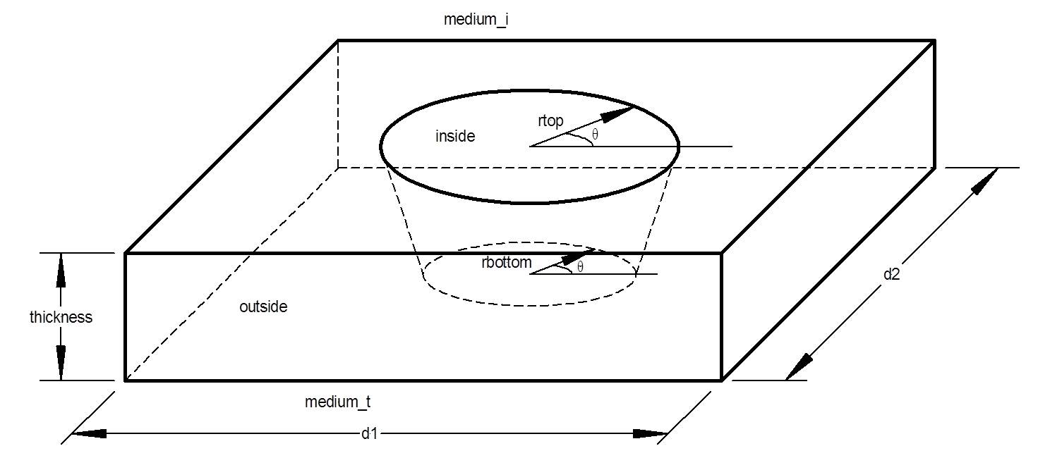
| rtop | Table | The radius of the top of the cylinder as a function of angle (in degrees) around the cylinder [µm]. If this value is a constant, then the top of the cylinder is a circle. If the radius exceeds the boundaries of the grating unit cell, the cylinder is truncated. | 0.05 |
| rbottom | Table | The radius of the bottom of the cylinder as a function of angle (in degrees) around the cylinder [µm]. If this value is a constant, then the bottom of the cylinder is a circle. If the radius exceeds the boundaries of the grating unit cell, the cylinder is truncated. | 0.05 |
| thickness | double | The thickness of the layer, which is also the height of the cylinder [µm]. | 0.05 |
| nlevels | int | The number of levels in the structure. | 10 |
| inside | dielectric_function | The optical constants of the interior of the cylinder, expressed as a complex number (n,k) or, optionally, as a function of wavelength. | (4.05,0.05) |
| outside | dielectric_function | The optical constants of the exterior of the cylinder, expressed as a complex number (n,k) or, optionally, as a function of wavelength. | (4.05,0.05) |
Rectangular_CrossGrating:
A binary grating consisting of rectangulars (or parallelograms) of one index of refraction embedded in a film of another index of refraction.
 |
|||
| medium_i | dielectric_function | The
optical constants of the incident medium, expressed as
a complex number (n,k) or, optionally, as a function of
wavelength. The material must be non-absorbing
(k=0). (Inherited from CrossGrating.) | 1 |
| medium_t | dielectric_function | The
optical constants of the transmitted medium, expressed as
a complex number (n,k) or, optionally, as a function of
wavelength. (Inherited from CrossGrating.) | (4.05,0.05) |
| d1 | double | The lattice constant along the 1st coordinate of the unit cell [µm]. (Inherited from Gridded_CrossGrating.) | 0.5 |
| d2 | double | The lattice constant along the 2nd coordinate of the unit cell [µm]. (Inherited from Gridded_CrossGrating.) | 0.5 |
| zeta | double | The off-perpendicular angle of the unit cell [deg]. The angle zeta is zero for
a rectangular unit cell. (Inherited from Gridded_CrossGrating.) | 0 |
| grid1 | int | The number of grid elements in the unit cell along the 1st coordinate. This parameter is optimally a power of 2.
However, the fast fourier transform algorithm that is used can accept any value, but its speed improves when the prime factors of grid1 are small. (Inherited from Gridded_CrossGrating.) | 1024 |
| grid2 | int | The number of grid elements in the unit cell along the 2nd coordinate. This parameter is optimally a power of 2.
However, the fast fourier transform algorithm that is used can accept any value, but its speed improves when the prime factors of grid2 are small. (Inherited from Gridded_CrossGrating.) | 1024 |
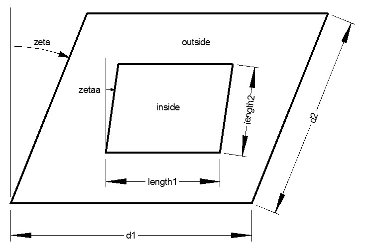
| length1 | Table | The length of one of the sides of the rectangles [µm]. If this size exceeds the boundaries of the grating unit cell, the rectangle is truncated. | 0.05 |
| length2 | Table | The length of the other sides of the rectangles [µm]. If this size exceeds the boundaries of the grating unit cell, the rectangle is truncated. | 0.05 |
| zetaa | Table | The angle of the parallelogram [degrees]. If this value is zero, then the shape is a rectangle. If the value is the same as zeta, the sides of the parallelogram line up with the unit cell. | 0 |
| thickness | double | The thickness of the layer, which is also the height of the cylinder [µm]. | 0.05 |
| inside | dielectric_function | The optical constants of the interior of the cylinder, expressed as a complex number (n,k) or, optionally, as a function of wavelength. | (4.05,0.05) |
| outside | dielectric_function | The optical constants of the exterior of the cylinder, expressed as a complex number (n,k) or, optionally, as a function of wavelength. | (4.05,0.05) |
Sphere_CrossGrating:
A grating consisting of a film in which an array of spheres is embedded.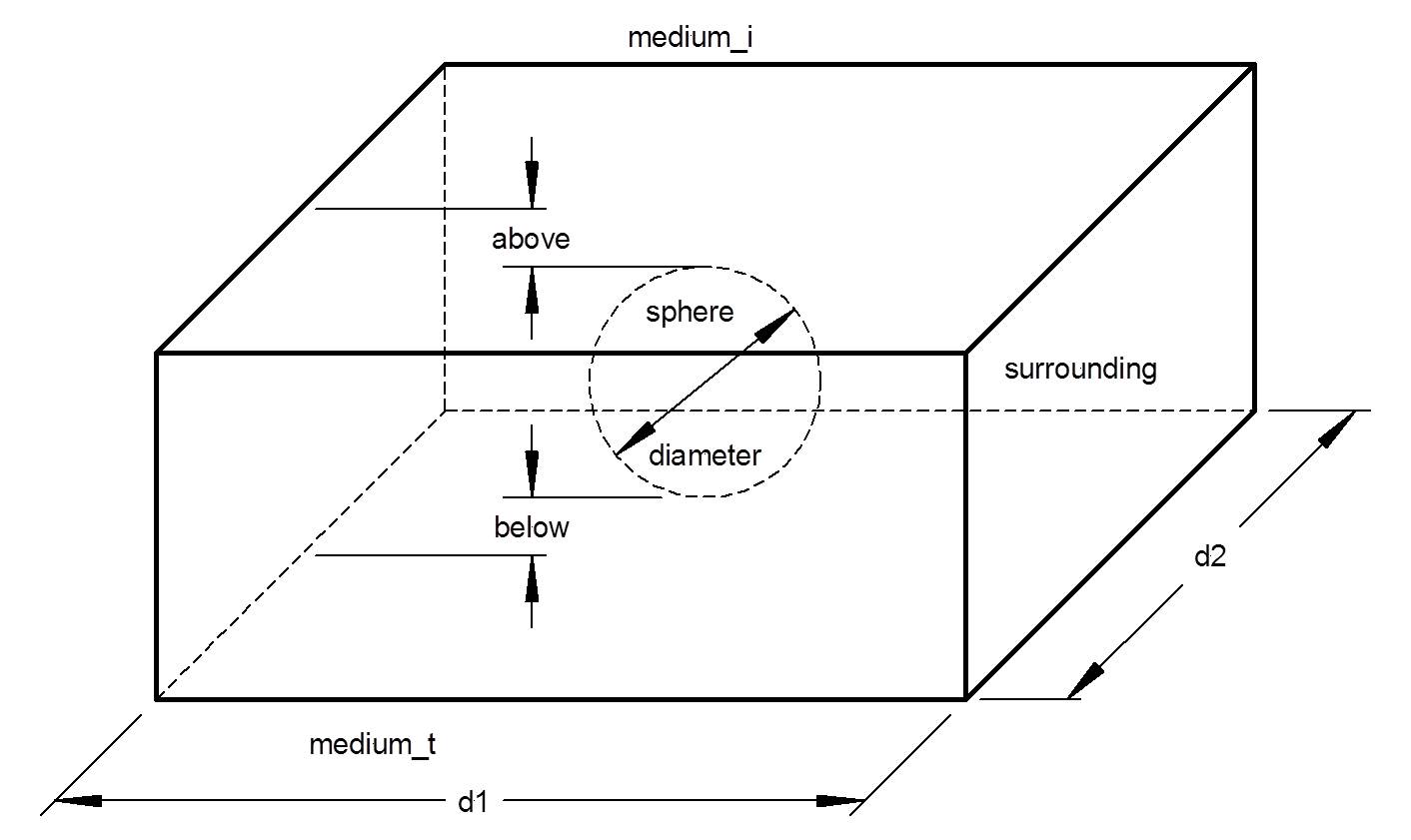 |
|||
| medium_i | dielectric_function | The
optical constants of the incident medium, expressed as
a complex number (n,k) or, optionally, as a function of
wavelength. The material must be non-absorbing
(k=0). (Inherited from CrossGrating.) | 1 |
| medium_t | dielectric_function | The
optical constants of the transmitted medium, expressed as
a complex number (n,k) or, optionally, as a function of
wavelength. (Inherited from CrossGrating.) | (4.05,0.05) |
| d1 | double | The lattice constant along the 1st coordinate of the unit cell [µm]. (Inherited from Gridded_CrossGrating.) | 0.5 |
| d2 | double | The lattice constant along the 2nd coordinate of the unit cell [µm]. (Inherited from Gridded_CrossGrating.) | 0.5 |
| zeta | double | The off-perpendicular angle of the unit cell [deg]. The angle zeta is zero for
a rectangular unit cell. (Inherited from Gridded_CrossGrating.) | 0 |
| grid1 | int | The number of grid elements in the unit cell along the 1st coordinate. This parameter is optimally a power of 2.
However, the fast fourier transform algorithm that is used can accept any value, but its speed improves when the prime factors of grid1 are small. (Inherited from Gridded_CrossGrating.) | 1024 |
| grid2 | int | The number of grid elements in the unit cell along the 2nd coordinate. This parameter is optimally a power of 2.
However, the fast fourier transform algorithm that is used can accept any value, but its speed improves when the prime factors of grid2 are small. (Inherited from Gridded_CrossGrating.) | 1024 |
| diameter | double | The diameter of the sphere [µm]. If the diameter causes the sphere size to exceed that of the unit cell, the sphere will be truncated. | 0.05 |
| above | double | The thickness of the medium that the sphere is embedded in which is above the sphere [µm]. This value must be non-negative. | 0.05 |
| below | double | The thickness of the medium that the sphere is embedded in which is below the sphere [µm]. This value must be non-negative. | 0.05 |
| nlevels | int | The number of levels into which the sphere is divided. The total number of levels used in the simulation will be the sum of nlevels and one for each of above and below which are non-zero. | 10 |
| sphere | dielectric_function | The optical constants of the sphere, expressed as a complex number (n,k) or, optionally, as a function of wavelength. | (1.5,0) |
| surrounding | dielectric_function | The optical constants of the material in which the sphere is embedded, expressed as a complex number (n,k) or, optionally, as a function of wavelength. | (1.5,0) |
Pyramidal_Pit_CrossGrating:
A surface-relief grating consisting of an array of square pyramidal pits. The materials medium_i and
medium_t are used to build this structure.
 |
|||
| medium_i | dielectric_function | The
optical constants of the incident medium, expressed as
a complex number (n,k) or, optionally, as a function of
wavelength. The material must be non-absorbing
(k=0). (Inherited from CrossGrating.) | 1 |
| medium_t | dielectric_function | The
optical constants of the transmitted medium, expressed as
a complex number (n,k) or, optionally, as a function of
wavelength. (Inherited from CrossGrating.) | (4.05,0.05) |
| d1 | double | The lattice constant along the 1st coordinate of the unit cell [µm]. (Inherited from Gridded_CrossGrating.) | 0.5 |
| d2 | double | The lattice constant along the 2nd coordinate of the unit cell [µm]. (Inherited from Gridded_CrossGrating.) | 0.5 |
| zeta | double | The off-perpendicular angle of the unit cell [deg]. The angle zeta is zero for
a rectangular unit cell. (Inherited from Gridded_CrossGrating.) | 0 |
| grid1 | int | The number of grid elements in the unit cell along the 1st coordinate. This parameter is optimally a power of 2.
However, the fast fourier transform algorithm that is used can accept any value, but its speed improves when the prime factors of grid1 are small. (Inherited from Gridded_CrossGrating.) | 1024 |
| grid2 | int | The number of grid elements in the unit cell along the 2nd coordinate. This parameter is optimally a power of 2.
However, the fast fourier transform algorithm that is used can accept any value, but its speed improves when the prime factors of grid2 are small. (Inherited from Gridded_CrossGrating.) | 1024 |
| side | double | The length of the base of the pyramidal pit [µm]. | 0.05 |
| depth | double | The depth of the pits [µm]. | 0.05 |
| nlevels | int | The number of levels in which the pits are subdivided. | 10 |
See also:
SCATMECH Home, CrossRCW_Model, CrossRCW_BRDF_Model
L. Li, "New formulation of the Fourier modal method for crossed surface-relief gratings," J. Opt. Soc. Am. A 14, 2758-2767 (1997).Include file:
#include "crossgrating.h"
#include "crossgrating2.h"
#include "gcross.h"
Source code:
crossgrating.cpp
crossgrating2.cpp
gcross.cpp
File format for Generic_CrossGrating
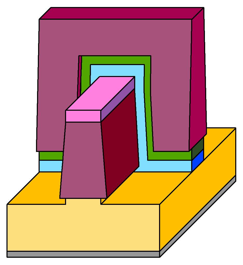
This section describes the file format required by Generic_CrossGrating. The file is a text file. We will illustrate the format of the file using an example grating structure, shown below. Dimensions are generic and parameters can be passed to the model at a later time using the pstring parameter. It is recommended that users familiarize themselves with the description for one dimensional gratings (in Generic_Grating) before moving on to two dimensional gratings. The grating description for a cross grating is very similar to that for a one dimensional grating. Instead of defining coordinates in two dimensions, with line segments separating regions, a two-dimensional grating requires coordinates in three dimensions, with polygons separating regions. While quite complicated structures can be described in this file format, the example we give below is fairly simple. We will consider a two-dimensional array of tetrahedral pits in a surface. A top-down view of this structure is shown below:
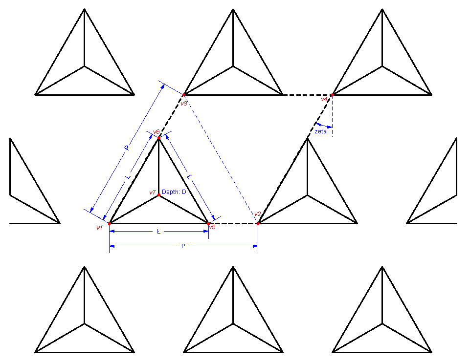
The solid black lines above denote the structure. The heavy black dashed parallelogram denotes the unit cell. The dimensions of the structure are given by the parameters P (for the unit cell side length), L (the base of the tetrahedrons), and D (the depth of the tetrahedrons). We assume for simplicity that the parallelogram is tilted by 30° (inner angles of 60° and 120°).
Like the grating description file for one-dimensional gratings, the grating description file for two-dimensional gratings is a plain-text file. In order to differentiate the two-dimensional grating from the one-dimensional grating description, the first word of the file must be CROSSGRATING for the two-dimensional grating. There are five blocks (PARAMETERS, WORKING, MATERIALS, VERTICES, and BOUNDARIES, in that order) of data in the file, and each begins with the name of the block and ends with the word END. In the following, the five blocks are described. In the text file, these blocks of data are listed consecutively and in order. Comments can be located anywhere in the file, are delimited by a semicolon (;), and run to the end of the line. Except insofar as linefeeds mark the end of comments, linefeeds can be placed anywhere in the file. The PARAMETERS section is essentially identical to that for a one-dimensional grating. In our example we would use (including the CROSSGRATING statement):
	  CROSSGRATING

          PARAMETERS
	        L     ; Length of base of pyramid
	        P     ; Length of unit cell (pitch)
	        D     ; Depth of pyramid
          END
WORKING Section:
The WORKING section is also essentially identical to that for a one-dimensional grating. The parameters zeta, d1, d2, and lambda are predefined by the values given in the class parameters. However, zeta, d1, and d2 can be overridden in the WORKING section. The value zeta is the angle (in degrees) that the unit cell is tilted from rectangular (see figure above, a rectangular lattice has zeta equal to 0°). The lattice constants are d1 and d2, where d1 is in the x (horizontal) direction, and d2 is the other lattice constant. The wavelength of the light is lambda and is assigned by CrossRCW_Model.
In our example, we might use:
         WORKING
	     x1   0
	     x6   L*cosd(60)
	     x3   P*cosd(60)
	     x5   L
	     x2   P
	     x4   x3+P
	     x7   x6

	     y1   0
	     y2   0
	     y5   0
	     y7   L/2*tand(30)
	     y6   L*sind(60)
	     y3  P*sind(60)
	     y4   y3

	     z1   0
	     z2   0
	     z3   0
	     z4   0
	     z5   0
	     z6   0
	     z7   -D

	     d1   P
	     d2   P
	     zeta 30
         END
In our example, x6 is the x coordinate of vertex v6 in the diagram. One in not required to use this scheme for defining the working variables; the author simply finds this scheme convenient when defining complex gratings.MATERIALS Section:
The MATERIALS section is also essentially identical to that for Generic_Grating. As for the one-dimensional grating, the two materials medium_i and medium_t are predefined and determined by the class parameters. Thus, for this simple grating, where we have no other materials, we would just use:
            MATERIALS
            END
Like the Generic_Grating, the keywords ANISO, MAGNETIC, and ANISOMAGNETIC can be used for anisotropic, magnetic, and anisotropic magnetic media. For cross gratings, when zeta is nonzero, the axes of the anisotropic media are the same as the unit cell vectors.VERTICES Section:
The VERTICES section is similar to that for a Generic_Grating, except that all vertices must have three coordinates, instead of two. The three coordinates, x, y, and z form a right-handed coordinate system, with x along the d1 side of the unit cell, and z pointing from the medium_t to medium_i. For our example, we would use:
            VERTICES
                  v1   (x1,y1,z1)
                  v2   (x2,y2,z2)
                  v3   (x3,y3,z3)
                  v4   (x4,y4,z4)
                  v5   (x5,y5,z5)
                  v6   (x6,y6,z6)
                  v7   (x7,y7,z7)
            END
Except for defining d1, d2, and zeta, we could have left out most of the variables in the WORKING section and defined the vertices by
            VERTICES
                  v1   (0,0,0)
                  v2   (P,0,0)
                  v3   (P*cosd(60),P*sind(60),0)
                  v4   (P*cosd(60)+P,P*sind(60),0)
                  v5   (0,L,0)
                  v6   (L*cosd(60),L*sind(60),0)
                  v7   (L*cosd(60),L*sind(60),-D)
            END
However, for a much more complicated grating, such a description can get very tedious.
BOUNDARIES Section:
The BOUNDARIES section, like that for the one-dimensional grating, is used to define all of the boundaries between materials. Unlike a one-dimensional grating, the boundaries must be defined with facets, rather than with line segments. There are two types of facets that are allowed: triangles and convex quadrangles. The convex quadrangles are further subdivided by the software into triangles, but are included to make some grating definitions easier. To define a triangle, for example, the one with vertices v1, v5, and v7, we would use:
v1 v5 v7 material_t material_iThat is, we list the three vertices, followed by the two materials. The order of the materials must correspond to the ordering of the vertices using a right-handed convention. That is, as one goes from the first vertex to the second vertex and then to the third vertex, with a right hand, the thumb will point from the first material to the second material. Reversing the two materials will create an error.
For a convex quadrangle, we use the flag QUAD, followed by four vertices, and followed again by the two materials. For example, the quadrangle defined by v5, v2, v3, and v6 (see light dashed blue line in the figure above), we would use:
QUAD v5 v2 v3 v6 material_t material_iThe vertices must be listed according to adjacent vertices on the quadrangle, and the right-hand rule is used for the ordering of the materials. Note that the quadrangle is divided into two triangles. Thus, the above QUAD statement is equivalent to
	        v5  v2  v3  material_t  material_i
	        v2  v3  v6  material_t  material_i
For that reason, it is best to ensure that all quadrangles are convex. That is, no internal angles of the quadrangles should be greater than 180°. Furthermore, it is best to use the QUAD designation only for vertices that are co-planar.
Thus, for the above structure, the BOUNDARIES section would be:
                BOUNDARIES
	              v1  v5  v7  material_t  material_i
	              v7  v5  v6  material_t  material_i
	              v1  v7  v6  material_t  material_i
	              QUAD  v5  v2  v3  v6  material_t  material_i
	              v2  v4  v3  material_t  material_i
                END
All boundaries within the unit cell must be defined. Any line passing in the z direction must pass consistently through boundaries, starting below the grating with material_t and ending above the grating with material_i. Any line passing in the x or y directions must pass consistently through boundaries, starting and ending with the same material. If a vertical boundary exists on the edge of the unit cell, then one should only specify the boundary on one side.
For More Information
SCATMECH Technical Information and Questions
Sensor Science Division Home Page
Sensor Science Division Inquiries
Website Comments
Current SCATMECH version: 7.22 (April 2021)