6. Buses
A single node on the electrical power system can be considered as a “bus”. A bus will have a single voltage and one or more currents flowing. Applications may use sensor data from a single bus or multiple buses. In the PMU framework, a single bus is a collection of modules. Each bus is made up of a collection of the following modules: * Event Module * Transformer Impairment Module (in development) * Sensor Impairment Module * Network Impairment Module * Status Impairment Module
As many buses as the computer’s memory and processors can support can be supported by the framework: launched and removed at any time
6.1. Bus Controller
During a test run, a software object called a “bus controller” is created for each bus. The bus controller object lasts only for the duration of the test run then is destroyed. All bus controllers run concurrently in their own threads. The bus controllers read the .ini files for each modules active plugin and concatenates all the plugin’s scriptlets together forming a single script, which the bus controller then executes. The scripts are always executed in the following module order: Event, Transformer (when developed), Sensor, Network, Status. it should be noted, that scripts from any module can access the information in any other module through a common API, So even though a script may be in one module’s .ini file, it can still contain commands that access the data in any other module.
The bus controllers use a queue to pass data from all the buses into the application where the data are aggregated to provide application input. Multiple busses write data into the same queue. Application plugins can use the base plugin’s aggregation function (where data is aggregated by timestamp) or can provide a custom aggregation function.
6.2. Bus Sequence Diagram
A UML sequence diagram illustrates the flow of key data between the modules in a single bus. Plugins can be developed with scriptlets that violate the sequence but the diagram illustrates the typical data flow. Each of the modules are represented as boxes along the top. Vertical lines represent time, beginning at the top and progressing towards the bottom. Data is transferred from one module to another as represented by labeled arrows.
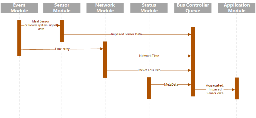
Figure 3: Bus Data Sequence Diagram
6.3. Event Module
As defined in 1.2.3, a power system event is represented by a mathematical function of time at each bus in the system from which the application receives sensor data or else by a collection of sensor data in a file. For each bus, one event module provides a set of ideal sensor data in an array of data structures called “Report Clusters.” To represent multiple buses, multiple Event Module instances will run in parallel. Each Event module will generate Sensor reports for the entire event before the data is output from the module. The event modules do not run in real time.
6.4. Sensor Module
Each instance of an event module will be paired with an instance of a Sensor Impairment Module. These modules accept ideal sensor data sets or ideal power system signal data and a set of impairment parameters and produce a collection of sensor data containing sensor errors as determined by the impairment parameters and the ideal input data.
6.5. Network Module
One set of Event and Sensor modules will be coupled with a Networking Impairment Module. The networking impairment modules receive Impairment Parameter and Loss Threshold information from the framework and create a Network Time vector and a Packet Loss array. These two sets of information will inform the Bus Controller module how to impair the incoming Report Cluster Arrays as a data stream might be impaired by network imperfections.
6.6. Status Module
Sensor reports often arrive at application with status, flags, or other metadata included. The Status Impairment Module creates a set of status data for each Sensor report being generated by the Event Module. These flags can be applied to data sent to the application. Plug-ins allow for various status impairment algorithms to be created by developers or end users.
6.7. Application
The application is an actor supported by the framework. Interfaces between the application and the framework will need to be custom built for each application so it is crucial that the framework designers work closely with the designers of the application to determine how the framework can support and interface with the application. Since hundreds or thousands of data sets will be input to the application for each event, the application must be suppor6ted by the framework in such a way that around the clock high speed testing can be run. Manual operation of the application per data set is not advised.